Otis Dynamics
Otis Dynamics Robot Arm
I lead mechanical design for the arms on ECHO, Otis Dynamics' dual-arm mobile robot for retail shelf replenishment.
- Role
- Co-Founder · Mechanical Design Lead
- Timeline
- Jun. 2026 – Present
- Status
- In development
Project overview
ECHO and the arm
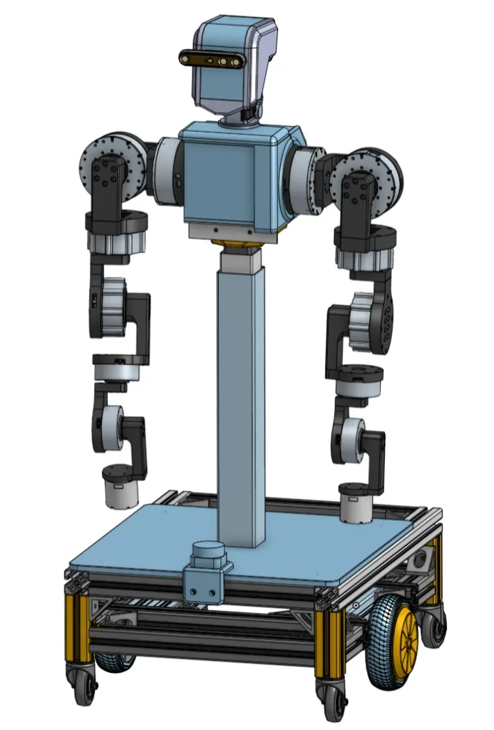
ECHO is our MVP. It is being built to stock retail shelves: two arms, a head with a vision system, a torso that translates up and down to reach every shelf height, and dexterous hands with force feedback so we can move things like produce and tell when a grasp is secure. The base is differential-drive so the robot can turn in place without extra mechanism for an MVP. Lidar and other sensors keep a basic estimate of where the robot is. Visual SLAM through the main cameras is the primary input for the outside world.
The design started in SolidWorks and moved to Onshape so the team could collaborate more easily. Arm actuators are RobStride units: affordable, and they produce enough torque for our requirements. A hoverboard controller runs the wheeled base. A Teensy 4.1 runs the torso, arms, and head. Everything feeds into a Jetson Orin Nano Super. We program and simulate the system in ROS 2.
Linkages and motor mounts are 3D printed, with the option to add carbon fiber tubes later so the arm deflects less when it is fully outstretched.
- SolidWorks
- Onshape
- RobStride
- Teensy 4.1
- CAN
- Jetson Orin Nano Super
- ROS 2 Jazzy
- Gazebo Sim
- RViz
- MoveIt
- 3D printing
Earlier proof of concept
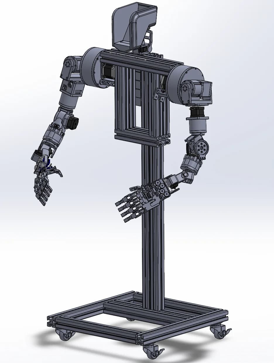
First system CAD
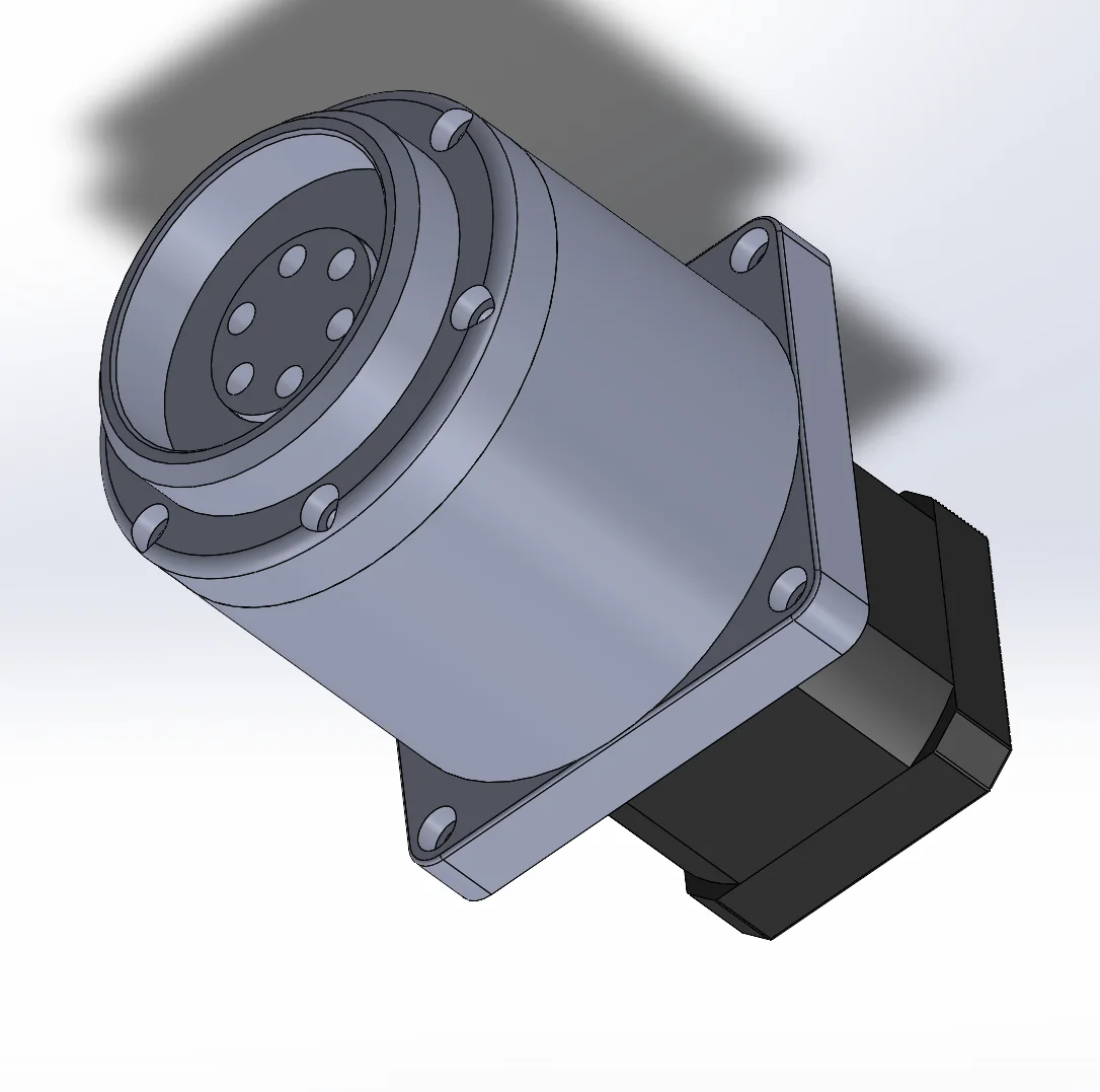
The first system CAD is an early proof of concept. That arm used cycloidal-drive gearboxes, servo-actuated fingers and hands, and was driven mainly by NEMA 17 and NEMA 23 stepper motors. It was a personal project to prove the idea before the current generation.
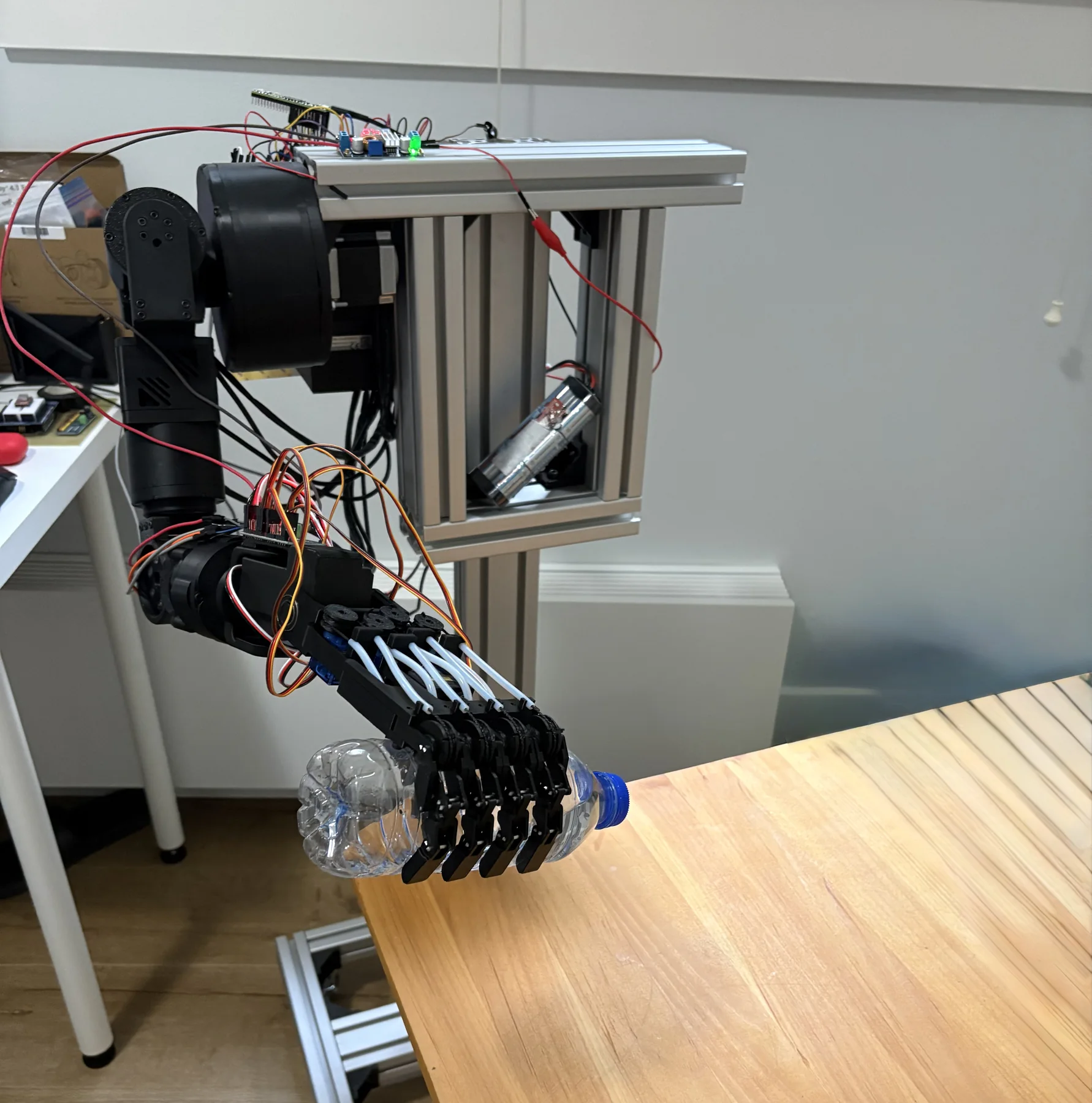
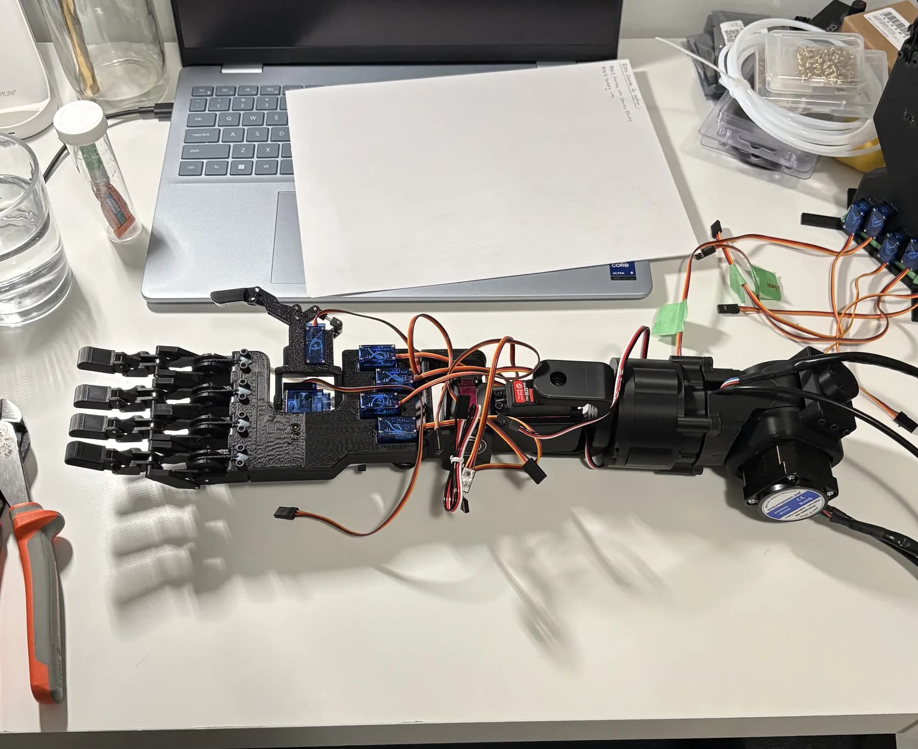
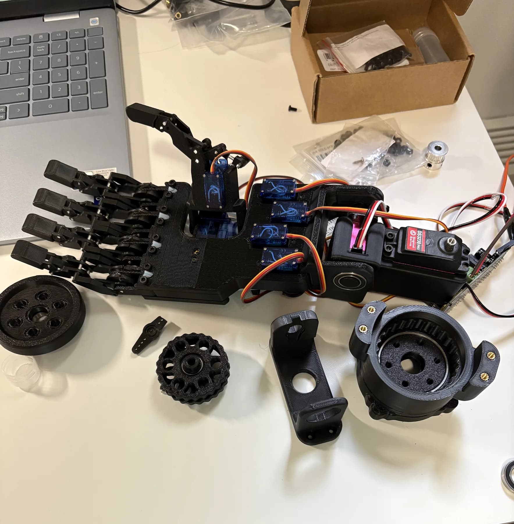
Earlier arm demonstration
A prior prototype used to test mechanism, wiring, and grasping. The current RobStride arm is a separate generation.
Requirements
Research and the actuator decision
Industry reading, my own reports and sketches, and Codex for collecting sources I then read myself got the requirements on paper. Consensus helped me find scientific papers.
The actuator decision was make versus buy. Options were building our own actuators and gearboxes, buying BLDC motors and making the gearboxes, buying motors plus gearboxes plus a driver and encoders, or purchasing complete actuators. Buying RobStride motors directly saved the most time and gave us an affordable way to start, while still forcing us to learn how they work. The arm uses RS00, RS02, RS03, and RS04 motors: two of each, except a single RS00.
Mechanical design
Onshape assembly
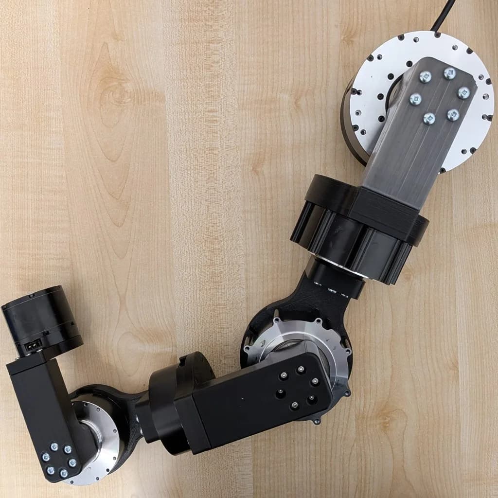
The assembly now lives in Onshape. The arm is designed so it is easy to assemble and manufacture: tools can reach the fasteners, and bolts and spacers are not buried. Brass heat-set inserts in the printed parts have been useful many times. A clearance hole plus a bolt into the insert makes a joint that is hard to pull apart by hand. Those connections keep the longer linkages attached to the motor mounts so the adapters do not fall off the arm.
The current arm is printed and assembled. It matches the Onshape model.
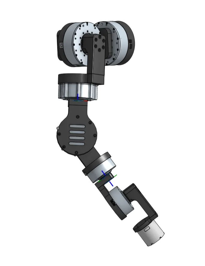
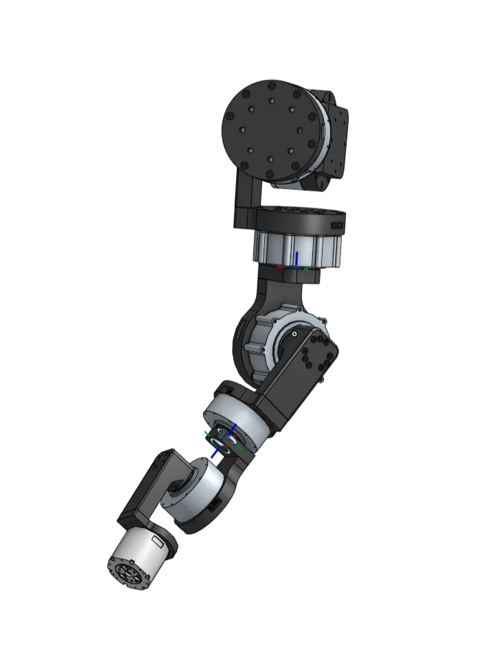
Manufacturing
Print orientation, PETG, and polycarbonate
A hard part of the arm design was optimizing for 3D-printed layer lines. FDM parts are anisotropic. Strength in the print plane comes from continuous filament roads. Strength through the stack depends on how well each layer fused to the one below. At a 0.24 mm layer height, a load that pulls those layers apart is testing weld strength, not bulk polymer strength. Parts loaded along the layer stack failed easily in testing. Printing so the layer lines sit perpendicular to the force, with multiple walls, produced parts I could not bend or break by hand.
PETG was the prototyping material. Polycarbonate is used for the final printed components. PETG is cheaper and easier to print, which makes it good for fit checks. PC is stronger and has much higher thermal resistance. It was harder to print: the Bambu Lab P2S chamber needs to sit around 50°C, with the bed at 110°C and the nozzle at 285°C. A 0.6 mm nozzle reduced clogging. The hotter bed and chamber helped the print stick without glue. It took a few tries to dial in. A 30 mm brim helped a lot and reduced warping as the chamber cooled and I removed the part.
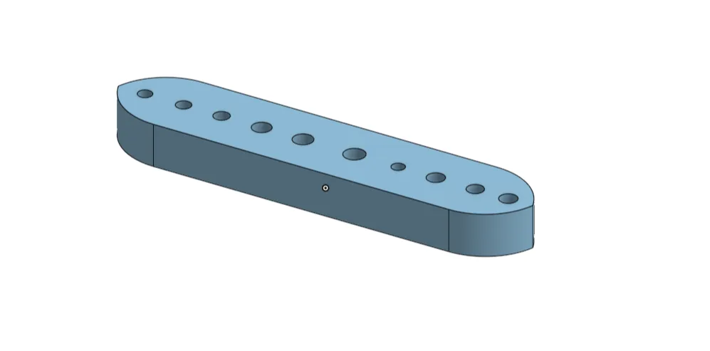
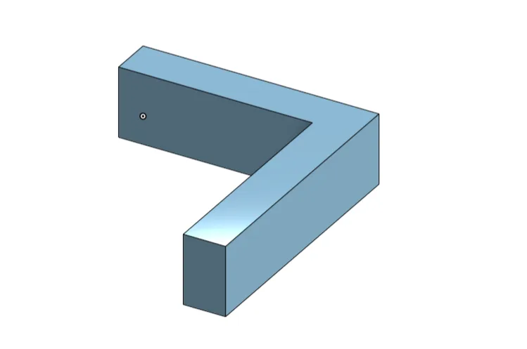
Tolerance checks used a coupon with holes of different sizes. A good clearance fit ended up matching Onshape's Loose preset for metric bolts, so a 4.8 mm hole for an M4. An L-bracket printed at different bed orientations showed how print direction changed strength.
Commissioning
Otis Motor Studio
Single-motor jogging first, then Motor Studio Multi once the motors were on one CAN trunk.
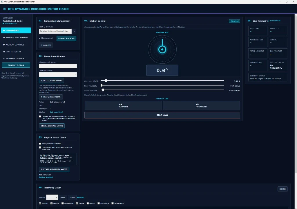
Codex helped me build Otis Motor Studio, a tool that sets position and jogs motors over CAN. The first setup was a USB-CAN adapter on a Windows 11 laptop, DC power to each motor, and CANH and CANL on the motor leads. That worked with the RS00, RS02, RS03, and RS04. Motor Studio went through many iterations until it ran consistently. It supports angular velocity and acceleration control, and it plots torque.
Otis Motor Studio Multi controls several motors at once over USB-CAN. That was required to test the wiring as the motors were connected together.
Motors were validated in a fixture I built for torque testing. The RS02 is rated for 6 Nm continuous. The motor was mounted with a lever arm that pressed on a food scale, and the manufacturer claims held up. A continuous test lifting and lowering a 5 lb weight many times showed how hot the motor got. It stayed efficient, and temperature did not look like a problem. Fans will still go in and around the arm so the motors do not overheat and lose torque.
After the CAD assembly was done, the parts order included screws, butt connectors, ring terminals, a lot of XT30 connectors, mixed-gauge wire, and the rest of the hardware.
Embedded control
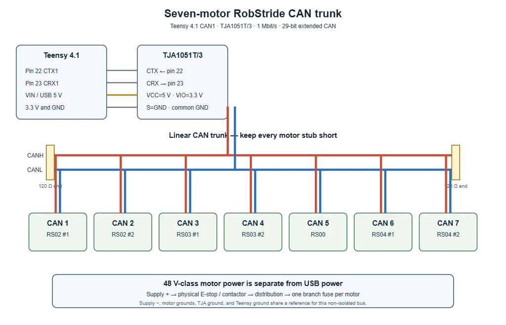
Teensy 4.1 CAN trunk
Early wiring tests used an Arduino Uno R4 WiFi with an MCP2515 to send CAN. That worked, but an Arduino should not be the controller on the MVP. The switch was to a Teensy 4.1. It is still programmable from the Arduino IDE, but it has better specifications. It will talk to the Jetson over serial and drive the motors directly.
A TJA1051 CAN transceiver on the Teensy stayed reliable as motors were added to the bus and did not drop frames.
Simulation
URDF, Gazebo, RViz, and the console
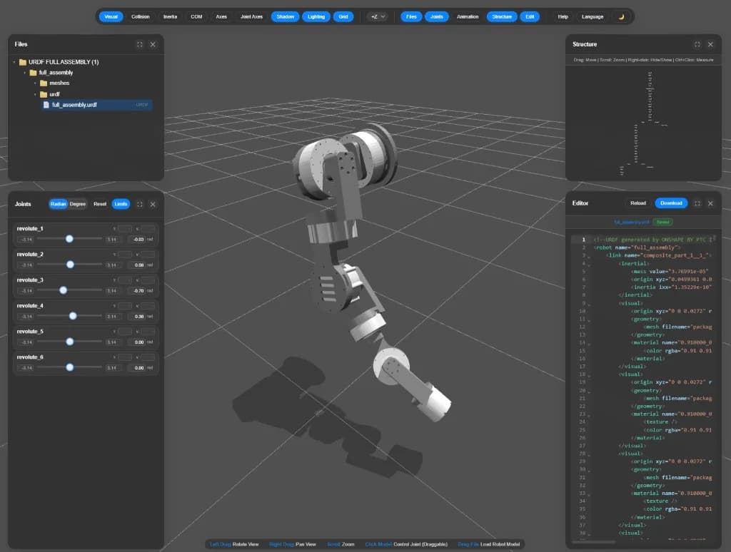
After the arm was assembled, I opened the Onshape URDF in ROS 2 Jazzy. For a first look I used the viewer at viewer.robotsfan.com. It loads the arm in a browser so I can move the joints and check collisions, which is much faster than standing up ROS 2 for that first check.
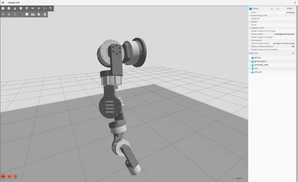
I run the arm in Gazebo Sim, the physics simulator. The screenshot is the arm on a table in that world.
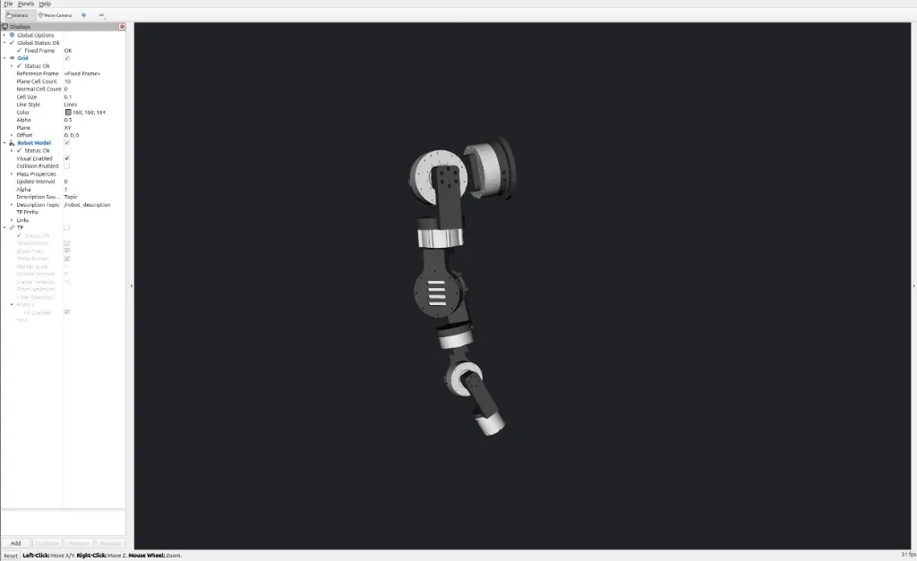
RViz is the ROS 2 visualizer. It does not run physics. It draws the model from /robot_description, and the pose matches Gazebo because both follow the same /joint_states.
Otis Arm Console is a local web app I built to drive the six revolute joints for presentations. It has sliders, jog buttons, and named poses such as simulation_zero, with positions in degrees. The page is labeled simulation control only.
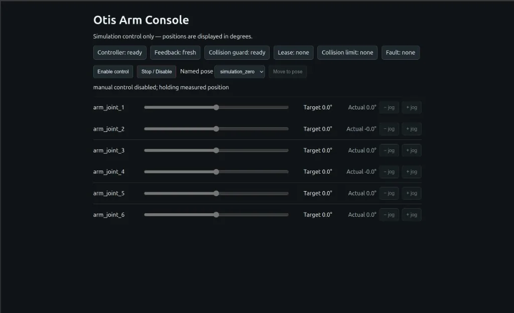
The screencast is that console next to Gazebo while I jog joints, then RViz and Gazebo side by side on the same pose. When a slider moves, the console shows joint target accepted, and the Actual angle lags the Target while the controller runs the trajectory.
The control loop in rqt_graph
rqt_graph in Nodes/Topics (active) is the running graph for this sim. Ovals are nodes. Rectangles are topics. Arrows go from a publisher to a topic, then to its subscribers.
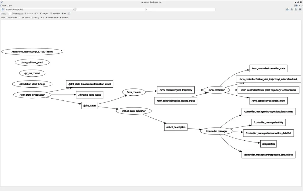
/joint_state_broadcaster
Reads the simulated joint state interfaces and publishes /joint_states (position, velocity, effort) and /dynamic_joint_states (every reported interface). It also publishes /joint_state_broadcaster/transition_event.
/arm_console
Subscribes to /joint_states so the web app knows the current pose, then publishes desired motion on /arm_controller/joint_trajectory.
/arm_controller
A joint trajectory controller. It subscribes to /arm_controller/joint_trajectory, the fire-and-forget topic interface, and publishes FollowJointTrajectory action feedback and status plus /arm_controller/controller_state and /arm_controller/transition_event. /arm_controller/speed_scaling_input is drawn as an input with no publisher in this snapshot. In ROS 2 Jazzy that topic can scale trajectory speed for position-based command interfaces.
/robot_state_publisher
Subscribes to /joint_states. With the URDF it publishes the 3D poses of the links on TF. In this graph it is also the publisher of /robot_description.
/controller_manager
Subscribes to /robot_description. It owns controller lifecycle and hardware interfaces, including arm_controller and the joint-state broadcaster. It publishes /controller_manager/activity, /diagnostics, and introspection topics.
/gz_ros_control, /simulation_clock_bridge, /arm_collision_guard, and the TF listener sit on the graph with no topic edges in this snapshot. rqt_graph hides some topics depending on filters. The console still reports Collision guard: ready. gz_ros2_control is the Gazebo plugin that instantiates a ros2_control controller manager and connects it to a Gazebo model.
Methodology
Engineering process
- 1
Requirements for shelf replenishment
Reach, grasping, torso travel, and a simple differential-drive base were set from the shelf-stocking task before the arm layout was locked.
- 2
Make versus buy for actuators
Custom actuators, partial drivetrains, and complete RobStride units were compared. Buying the motors got us on the bench sooner and still required learning the CAN interface.
- 3
CAD in Onshape
The assembly moved from SolidWorks to Onshape for team collaboration, with fastener access and heat-set inserts designed in from the start.
- 4
Print orientation and materials
PETG was used for fit checks. Polycarbonate, layer orientation, and wall count were used for loaded parts.
- 5
Bench commissioning
Otis Motor Studio and a torque fixture were used to jog motors, plot torque, and check the RS02 continuous rating before the arm was wired as a group.
- 6
Teensy CAN control
An Arduino and MCP2515 proved the bus. A Teensy 4.1 and TJA1051 now drive the motors and will talk to the Jetson over serial.
- 7
URDF, then ROS 2
The Onshape URDF was checked in a browser first. The arm now runs in Gazebo Sim and RViz on ROS 2 Jazzy, with Otis Arm Console sending joint trajectories.
Research and findings
What changed the design
Print strength follows layer orientation
Loading along the 0.24 mm layer stack tests interlayer weld strength. Orienting walls perpendicular to the load produced parts I could not break by hand.
Buying actuators got us moving sooner
Building gearboxes in-house would have taken longer. RobStride units were affordable enough to start, and we still had to learn the motors in detail.
PETG for fit, polycarbonate for load and heat
PETG was faster to print for prototypes. PC needed a ~50°C chamber, 110°C bed, 285°C nozzle, a 0.6 mm nozzle, and a 30 mm brim, but it is stronger and handles heat better.
Arduino proved the bus; Teensy is the controller
The Uno R4 and MCP2515 were enough to transmit CAN. The Teensy 4.1 is the MVP controller because it has better specifications and stayed reliable as motors were added.
A browser URDF check is faster than ROS 2
Loading the Onshape export at viewer.robotsfan.com caught joint and collision issues before standing up Gazebo and RViz.
Heat-set inserts hold printed joints
A clearance hole into a brass insert makes a joint that is hard to pull apart by hand, which keeps motor mounts on the longer linkages.
Build log
Build log
Last updated September 2026.
July 2026
CompleteResearch and requirements
Defined shelf-replenishment motions, wrote reports and sketches, and compared actuator approaches.
Late July 2026
CompleteEarly concept
Built the first system CAD around cycloidal gearboxes, servo hands, and NEMA 17 / NEMA 23 steppers as a proof of concept.
August 2026
CompleteActuator validation
Commissioned RobStride motors in a fixture, checked the RS02 6 Nm continuous rating on a food-scale lever, and ran a 5 lb lift-and-lower heat test.
August 2026
CompleteProcurement
Ordered screws, connectors, XT30s, mixed-gauge wire, and the rest of the hardware after the CAD assembly was in place.
Late August 2026
CompleteOnshape arm CAD
Moved the assembly to Onshape, designed for tool access and heat-set inserts, and printed PETG fit checks before PC parts.
September 2026
CompleteOtis Motor Studio
Built single-motor and multi-motor CAN tools for position, velocity, acceleration, and torque plots over USB-CAN.
September 2026
CompleteTeensy CAN trunk
Moved from an Arduino and MCP2515 to a Teensy 4.1 and TJA1051. The bus stayed reliable as motors were added.
September 2026
CompleteArm assembly and URDF
Assembled the arm, checked the Onshape URDF in a browser, and started a ROS 2 joint-control web app with MoveIt.
September 2026
CompleteROS 2 Jazzy simulation
Loaded the arm in Gazebo Sim and RViz, drove joints from Otis Arm Console, and captured the rqt_graph control loop.
Current
In progressTorso, base, and system wiring
Physical integration and wiring of the arm with the torso and base. Covers wait until the robot is functioning and wired. Fans are planned around the arm.
Current work
Next steps
- →Physically integrate and wire the arm with the torso and base.
- →Install covers after the robot is functioning and wired.
- →Add fans in and around the arm for cooling.
- →Use carbon fiber tubes if deflection with the arm fully outstretched needs it.